顯示具有 Arduino 標籤的文章。 顯示所有文章

2015年1月21日 星期三

Intel Edison Board 之五 Upload出現的問題...

好不容易才把閃退的問題搞定,一上傳檔案居然又出現錯誤,

為了不浪費大家捲頁面時間,錯誤訊息臚列在最下面段落。
弄了老半天還是一樣...........

後來發現,原來upload的port弄錯了,得指到virtual port才能正確upload,
正確請參照下圖
終於..........
arduino界的"Hello world!".....Blink上場


======================================================
錯誤訊息
======================================================
Binary sketch size: 76,099 bytes (of a 10,000,000 byte maximum) - 0% used
#!/bin/sh
echo "starting download script"
starting download script
echo "Args to shell:" $*
# ARG 1: Path to lsz executable.
# ARG 2: Elf File to download
Args to shell: D:\arduino-1.5.3-Intel.1.0.4/hardware/tools/x86/bin C:\Users\admin\AppData\Local\Temp\build8676981779102617934.tmp/Blink.cpp.elf COM3
COM PORT 3
Converted COM Port COM3 to tty port /dev/ttyS2
Sending Command String to move to download if not already in download mode
# ARG 3: COM port to use.
#path contains \ need to change all to /
path_to_exe=$1
fixed_path=${path_to_exe//\\/\/}
#COM ports are not always setup to be addressed via COM for redirect.
Deleting existing sketch on target
#/dev/ttySx are present. Howwever, COMy -> /dev/ttySx where x = y - 1
com_port_arg=$3
com_port_id=${com_port_arg/COM/}
echo "COM PORT" $com_port_id
tty_port_id=/dev/ttyS$((com_port_id-1))
echo "Converted COM Port" $com_port_arg "to tty port" $tty_port_id
echo "Sending Command String to move to download if not already in download mode"
echo "~sketch download" > $tty_port_id
D:\arduino-1.5.3-Intel.1.0.4/hardware/arduino/edison/tools/izmir/clupload_win.sh: line 24: /dev/ttyS2: Permission denied
#Move the existing sketch on target.
echo "Deleting existing sketch on target"
$fixed_path/lsz.exe --escape -c "mv -f /sketch/sketch.elf /sketch/sketch.elf.old" <> $tty_port_id 1>&0
D:\arduino-1.5.3-Intel.1.0.4/hardware/arduino/edison/tools/izmir/clupload_win.sh: line 28: /dev/ttyS2: Permission denied
# Execute the target download command
#Download the file.
host_file_name=$2
$fixed_path/lsz.exe --escape --binary --overwrite $host_file_name <> $tty_port_id 1>&0
D:\arduino-1.5.3-Intel.1.0.4/hardware/arduino/edison/tools/izmir/clupload_win.sh: line 34: /dev/ttyS2: Permission denied
#mv the downloaded file to /sketch/sketch.elf
Moving downloaded file to /sketch/sketch.elf on target
target_download_name="${host_file_name##*/}"
echo "Moving downloaded file to /sketch/sketch.elf on target"
#$fixed_path/lsz.exe --escape -c "cp sketch /sketch/sketch.elf" <> $tty_port_id 1>&0
$fixed_path/lsz.exe --escape -c "mv $target_download_name /sketch/sketch.elf; chmod +x /sketch/sketch.elf" <> $tty_port_id 1>&0
D:\arduino-1.5.3-Intel.1.0.4/hardware/arduino/edison/tools/izmir/clupload_win.sh: line 40: /dev/ttyS2: Permission denied
===============================================================

2015年1月19日 星期一

Intel Edison Board之三 Getting Start~

期末考第二天,先來把硬體連接搞定
1.當然先把edison board裝到擴充板上,這部份上星期到貨時已經完成


2.兩種供電方式,一種透過電源接頭,第二種使用usb micro B接頭
    (以下圖片來自http://www.intel.com/support/edison/sb/CS-035336.htm)


3.擴充板上的兩個USB micro A type接頭簡單說明如下

靠近switch的micro usb
    1.供電
    2.ethernet over usb
    3.upload arduion sketches
    4.update the firmware by using the board as a storage device,like a flash drive

靠板子邊緣的micro usb
    建立串列埠連線用
=============================================================.

這次先使用micro usb供電,因此板上的switching要撥往靠近micro usb側

接上usb後,板上DS1綠色LED恆亮,edison board開始開機程序;
第一次連接上電腦時,會安裝部分驅動程式,接著電腦會新增一部drive,名為Edison

接著再接上另一條USB,同樣的會自動安裝驅動程式,並模擬為電腦上的com port
這裡為com 3

此時仍會有兩個裝置的driver未安裝,須另行下載驅動程式Windows Driver setup 1.0.0(http://downloadmirror.intel.com/24271/eng/IntelEdisonDriverSetup1.0.0.exe),
安裝後,再至裝置管理員,將其驅動

===================================================================
完成連接後,透過終端機程式,來測試一下連線,這裡使用putty
開啟putty,連線設定如下

按下Open,開啟終端機視窗後再按一下enter

登入帳號: root,沒有密碼

可以使用指定: configure_edison --help,修改部分設定

====================================================================
更換(新)韌體
更新韌體時,連接硬體後,開啟檔案總管,進入Edison的磁碟中,將所有檔案刪除,
接著至intel網站下載最新版韌體https://communities.intel.com/docs/DOC-23242
這裡使用Yocto complete image(linux-Yocto)

下載後解開,並全部copy到Edison的磁碟中

接著使用終端機putty進入edison board,使用指令 reboot ,
即可重新啟動並進行韌體刷新(*此動作會清除edison board所有資料,包含configuration setting)
更新完成


2015年1月16日 星期五

Intel Edison board之二

依據Intel說明,大致規格如下

  • 採 22nm製程,silvermont微架構的Soc,包含一顆dual-core CPU與single core的MCU。
  • 整合無線網路、藍芽、記憶體與儲存空間。
  • 透過板子上的70pin連接頭,支援超過30支工業標準的I/O interface。
  • 支援for Yocto Linux*, Arduino*, Python*, Node.js*, and Wolfram*。
  • 開放式的社群軟體開發工具
    • Silvermont 微架構的特性說明
      • 全新亂序 (out-of-order) 執行引擎,帶來先進的單執行緒 (single-threaded) 運算效能¹。
      • 新的多核心與系統互連架構,最多可擴充至八核心,進一步推升效能以支援高頻寬、低延遲、以及更有效率的亂序處理模式,打造出更均衡化且快速反應的系統。
      • 新的 IA 指令集與技術,帶來進階的效能、虛擬化、以及安全管理功能,藉以支援各類型的產品。這些指令集建立在英特爾現有的 64 位元支援技術以及已安裝的 IA 軟體基礎。
      • 增強的電源管理功能,包括新的智慧遽增技術 (intelligent burst technology)、各種低功耗休眠狀態、以及運用英特爾 3-D 電晶體帶來更廣的動態運作範圍。Intel® Burst Technology 2.0 支援單核與多核心晶片,提供更快的反應速度進而增進電源使用效益


      •  

Intel Edison board之一 Intel針對穿戴式裝置的快速原型開發板

離上次寫東西又相隔好久,這一次先把實物照片貼一貼,晚點再來介紹~
Intel去年(2014)第四季上市的開發板,
Intel Edison~
星期三訂,今天(星期五)到,2天時間就從米國到達這個小鄉鎮,
現代的快遞真是無話可說...

不免俗,先來開箱...

接著來看看Intel Edison片包含CPU、記憶體、網路、藍芽等等的小板子,
就跟5元硬幣差不多

當然上面這板子要直接用,實在...有點難度,所以另外買了for arduion的擴充板
下圖左下角處,就是要安裝Edison的位置

 兩者合照


合體~~

在此先打住,晚點再來寫規格與介紹;開會去....

2014年11月25日 星期二

arduino_LED練習

有空再來打程式碼說明,直接看source code與執行結果

1.LED單向移動
01int led[] = {0,1,2,3,4,5,6};
02int i;
03int j=0;
04void setup()
05{
06  for (i=0;i<7;i++)
07  {
08    pinMode(led[i],OUTPUT);
09  }
10}
11void loop()
12{
13  for(i=0;i<7;i++)
14  {
15    digitalWrite(led[i],HIGH);      //因為IO板的LED接為共陽極,故此處為了將所有LED設為熄滅
16  }                                            //因此第15行digitalWrite寫入為HIGH,以下依此類推
17  digitalWrite(led[j],LOW);
18  delay(200);
19  j++;
20  if (j==7)
21  j=0;
22}


===========================================================
2.LED左右來回移動
01int led[] = {0,1,2,3,4,5,6};
02int i;
03int j=0;
04int dir=0;
05void setup()
06{
07  for (i=0;i<7;i++)
08  {
09    pinMode(led[i],OUTPUT);
10  }
11
12}
13void loop()
14{
15  for(i=0;i<7;i++)
16  {
17    digitalWrite(led[i],HIGH);
18  }
19  digitalWrite(led[j],LOW);
20  delay(80);
21  if (dir==0)
22  {
23    if (j==6)
24      dir=1;
25    else
26      j++;
27  }
28  else
29  {
30      if(j==0)
31        dir=0;
32      else
33       j--;
34  }
35}

===========================================================
3.左右移動並閃爍
01int led[] = {0,1,2,3,4,5,6};
02int i;
03int j=0;
04int dir=0;
05void setup()
06{
07  for (i=0;i<7;i++)
08  {
09    pinMode(led[i],OUTPUT);
10  }
11
12}
13void loop()
14{
15  for(i=0;i<7;i++)
16  {
17    digitalWrite(led[i],HIGH);
18  }
19  for (i=0;i<4;i++)
20  {
21    digitalWrite(led[j],LOW);
22    delay(40);
23    digitalWrite(led[j],HIGH);
24    delay(40);
25  }
26  delayMicroseconds(100);
27  if (dir==0)
28  {
29    if (j==6)
30      dir=1;
31    else
32      j++;
33  }
34  else
35  {
36      if(j==0)
37        dir=0;
38      else
39       j--;
40  }
41}


==========================================================
4.遞增再遞減
01int led[] = {0,1,2,3,4,5,6};
02int i;
03int j=0;
04void setup()
05{
06  for (i=0;i<7;i++)
07  {
08    pinMode(led[i],OUTPUT);
09  }
10
11}
12void loop()
13{
14  for(i=0;i<7;i++)
15  {
16    digitalWrite(led[i],HIGH);
17  }
18  delay(500);
19  for (j=0;j<7;j++)
20  {
21  digitalWrite(led[j],LOW);
22  delay(100);
23  }
24  for (j=0;j<7;j++)
25 {
26  digitalWrite(led[j],HIGH);
27 delay(100);
28 }
29
30
31}


2014年11月24日 星期一

arduino 之初步練習

拖了很久,總該要有第一步...
這裡拿了利基的板子(OZONE,使用ATmega32u4,相容於arduino的leonardo板),來做為示範
有關ozone的資料再參考利基的網頁說明。
UNO的微控器用的是ATmega328,
Leonardo用的是ATmega32u4

OZONE為中間紅色板子,旁邊為一般的I/O實驗板
不囉嗦,直接看入門範例 
在編輯環境中選擇 File->Examples->01.Basics->Blink

內建範例程式碼如下
=================================================================
01  /*
02    Blink
03    Turns on an LED on for one second, then off for one second, repeatedly.
04   
05    This example code is in the public domain.
06   */
07   
08  // Pin 13 has an LED connected on most Arduino boards.
09  // give it a name:
10  int led = 13;
11  
12  // the setup routine runs once when you press reset:
13  void setup() {                
14    // initialize the digital pin as an output.
15    pinMode(led, OUTPUT);     
16  }
17  
18  // the loop routine runs over and over again forever:
19  void loop() {
20    digitalWrite(led, HIGH);   // turn the LED on (HIGH is the voltage level)
21    delay(1000);               // wait for a second
22    digitalWrite(led, LOW);    // turn the LED off by making the voltage LOW
23    delay(1000);               // wait for a second
24  }
====================================================================
這裡使用板子上內建的一顆LED燈做為測試示範,該燈接於P13腳,在沒有任何的外接
電路下,即可練習初步指令。
本例執行結果,板上LED燈以每秒亮滅閃爍顯示


2014年9月19日 星期五

Arduino:Leonardo與Uno的比較

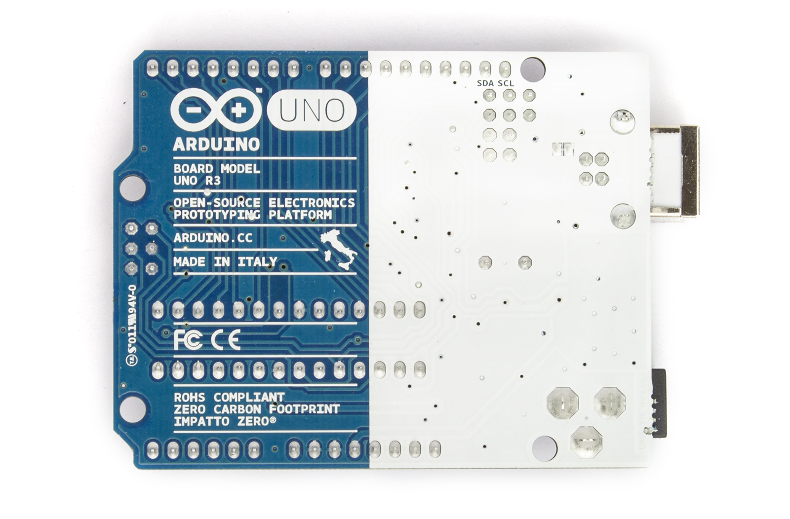
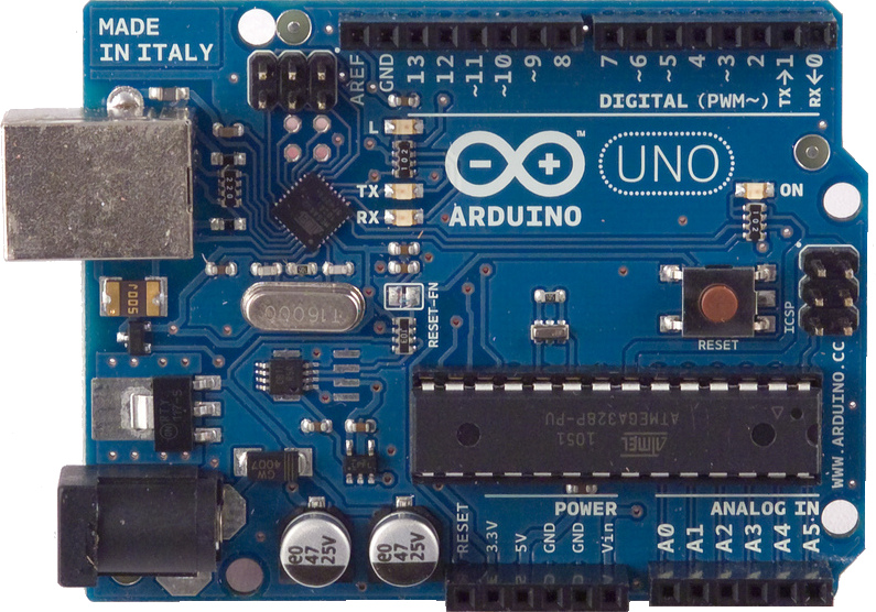
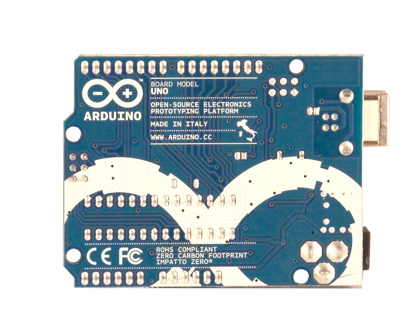
Arduino Uno R3 Front and Back

Arduino Uno R2 Front

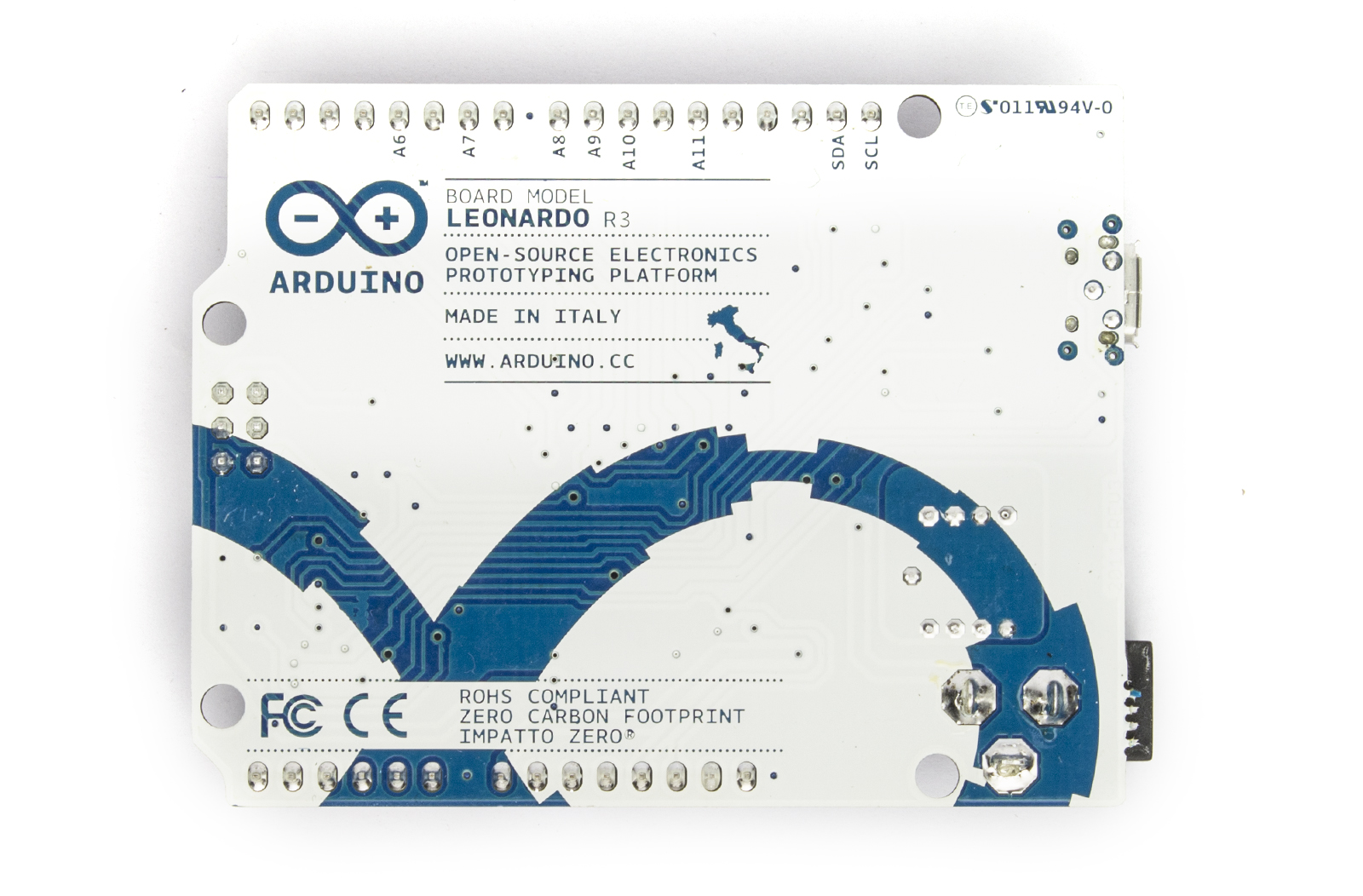
Arduino Uno Front  and Back
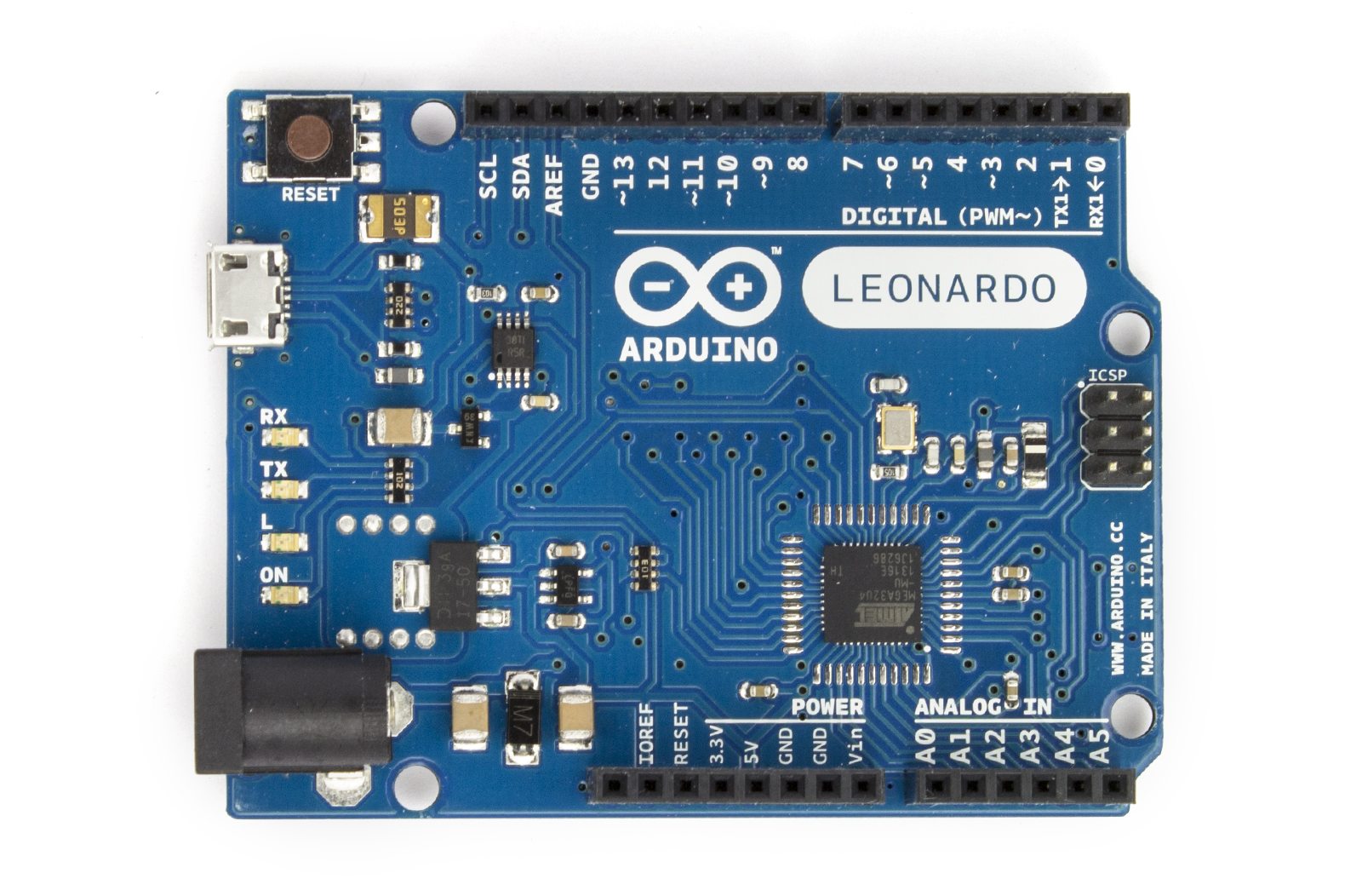
Arduino Leonardo Front with headers and Rear

UNO: 
MicrocontrollerATmega328
Operating Voltage5V
Input Voltage (recommended)7-12V
Input Voltage (limits)6-20V
Digital I/O Pins14 (of which 6 provide PWM output)
Analog Input Pins6
DC Current per I/O Pin40 mA
DC Current for 3.3V Pin50 mA
Flash Memory32 KB (ATmega328) of which 0.5 KB used by bootloader
SRAM2 KB (ATmega328)
EEPROM1 KB (ATmega328)
Clock Speed16 MHz


MicrocontrollerATmega32u4
Operating Voltage5V
Input Voltage (recommended)7-12V
Input Voltage (limits)6-20V
Digital I/O Pins20
PWM Channels7
Analog Input Channels12
DC Current per I/O Pin40 mA
DC Current for 3.3V Pin50 mA
Flash Memory32 KB (ATmega32u4) of which 4 KB used by bootloader
SRAM2.5 KB (ATmega32u4)
EEPROM1 KB (ATmega32u4)
Clock Speed16 MHz


Uno的bootloader約0.5 KB
Leonardo的bootloader約4 KB,


Uno與Leonardo板子的尺寸大小、排母數目與位置,都一樣,但功能有所不同。

數位腳位,板子上方有14個(標示為0~13),其中6個可PWM,以「~」額外標示;
解析度8位元
       UNO:3、5、6、9、10、11。
Leonardo:3、5、6、9、10、11、13。

類比輸入腳位:
Uno板子下方有6個(標示為A0~A5),解析度10位元。
Leonardo多了6個,A6~A11(位於數位腳位4、6、8、9、10、12)。

I2C/TWI介面:
        Uno:SDA(A4、SDA)與SCL(A5、SCL)。
Leonardo:SDA(2、SDA)  與SCL(3、SCL)。
        UNO R3上方插槽較R2多兩腳(與Leonardo插槽相同),如下圖示(來源:網昱多媒體 Arduino UNO介紹),新增的SCL和SDA插孔,分別和類比腳位A5與A4相連,新增這兩個插孔的好處是,做實驗時從板子的標示(註:標示在板子背後),能立即分辨SCL和SDA。
Arduino UNO控制板的接腳說明


 SPI介面:
Uno:SS(10)、MOSI(11)、MISO(12)、SCK(13)。
Leonardo跟Uno不同,SPI不在數位腳位,MOSI、MISO、SCK都在ICSP上,SS則位於板子左邊與RX LED相連。

外部中斷:
Uno:2(int.0)、3(int.1)。
Leonardo:3(int.0)、2(int.1)、0(int.2)、1(int.3)、7(int.4)。

Serial(序列介面):
Uno:RX(0)與TX(1)連接8U2/16U2(USB轉TTL Serial的晶片),在程式裡以Serial物件存取。Leonardo:在程式裡Serial物件代表USB CDC(Connected Device Class),而Serial1物件才是RX(0)與TX(1)。Leonardo事實上擁有兩個序列埠,一個模擬而成的虛擬序列埠(不管是在電腦端還是在微控制器端),連接USB連線,另一個則是微控制器本身原本擁有的UART硬體。

因Leonardo使用內建USB功能的ATmega32U4,擁有非常強大的bootloader,除了可作為虛擬序列埠(COM port),也可模擬成USB鍵盤與滑鼠(標準的HID裝置,無需驅動程式)。連接Leonardo與電腦時,系統就會出現三個新硬體裝置:虛擬序列埠、USB鍵盤、USB滑鼠。其實Uno也可以模擬USB鍵盤與滑鼠,但必須透過DFU模式修改8U2/16U2的韌體。

自動軟體重置:
Uno:8U2/16U2的DTR連接到Atmega328P的重置線路。
Leonardo:當以1200鮑率開啟虛擬序列埠並關閉時就重置。

Uno因有一顆獨立晶片負責USB轉TTL Serial,所以當主晶片重置時,該連線並不會斷掉,但Leonardo會,原本若開啟電腦端的序列埠監控視窗,Uno就會重置,但Leonardo不會,以至於在setup()從序列埠傳出的資料,可能不會出現在電腦端,所以通常會加上while (!Serial);等待開啟序列埠。

因為Leonardo重置時虛擬序列埠會消失,所以在上傳(燒錄)時,Arduino IDE會等待,直到出現新的虛擬序列埠,然後再進行上傳動作。

資料來源: